
Carving a Four Foot Tall Tiki Skulpture
by Greg Flanagan • May 27, 2014 • Design, shopbot • 0 Comments
I was recently asked to build a tiki head statue for a local restaurant. The lure of rum-soaked drinks made the job hard to turn down. I figured my recently acquired CNC router made the task possible for me since I have no formal sculpture training. It seemed simple—before I realized what I was getting into. The project forced me to explore the Z limits of my machine and taught me how to incorporate maximum depth of cut into my 3D machining project planning.
THE GENERAL PLAN
- Review design options with the client
- Download and modify the model
- Slice the 3D model into layers
- Carve the layers
- Reassemble the layers
- Complete final shaping and finish
Find a 3D Model
I started my search for a model at the Sketchup 3D Warehouse. Not finding what I wanted there, I found some great 3D models at turbosquid.com and brought the screenshots to my clients. They picked the one they liked.
TWEAK THE MODEL FOR MACHINING
I downloaded the file and did a little 3D editing in Rhinoceros to make the shape machinable. I made the eyes and area between the teeth less deep and I modified a few other contours to make machining easier. I then set off to figure out how the heck I would build the thing.
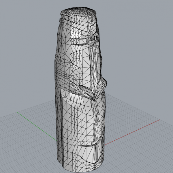 Editing the Tiki 3D model in Rhino.
Foam or Wood?
The plan called for a 4′ tall, 18″ diameter statue. I had considered using polystyrene foam. It’s fairly inexpensive, light and easy to cut on a CNC router. Initially, I had planned to paint and coat the finished foam to make it look like weathered wood. This plan seemed solid—until I realized I don’t possess the skill to faux paint foam to mimic wood.
I then decided I would construct this thing out of actual wood. I am a woodworker, after all, so I know what it takes to fix the inevitable mistake. I checked out the local lumber yard and found a great deal on some 10′x6″x6″ cedar timbers. Since the original plan was to place this on a patio, cedar was a great choice. It is naturally weather, rot, and insect resistant.
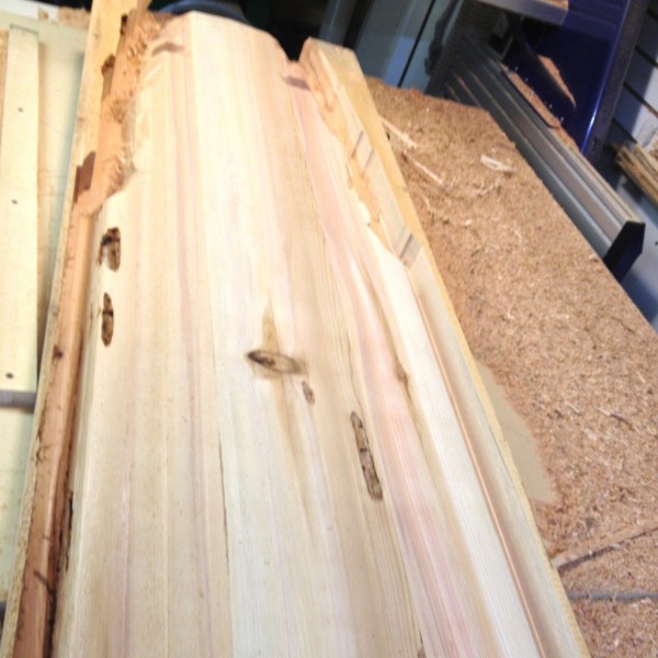
I brought the planks home and began breaking them down so I could glue up three 4′ x 18″ x 6″ slabs.
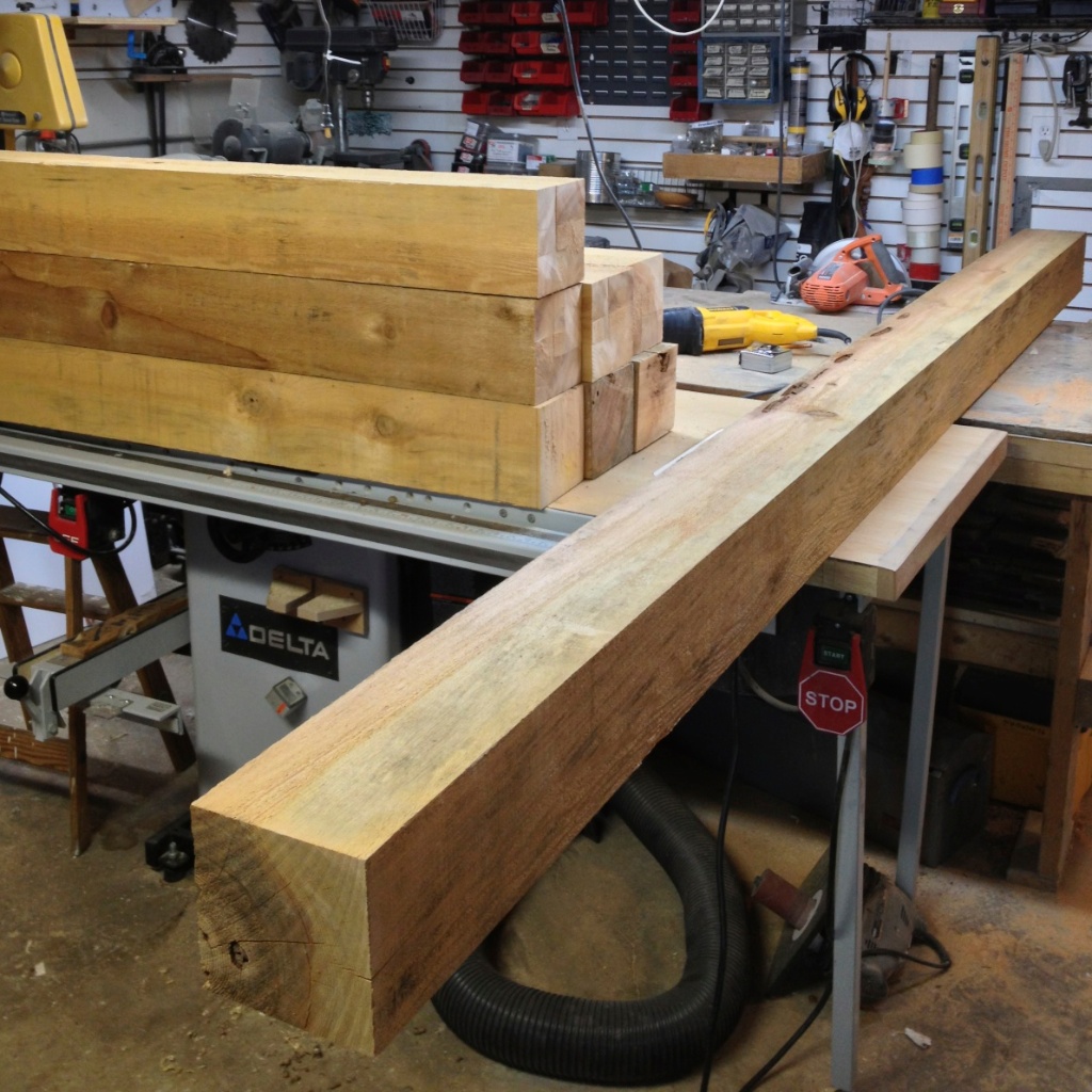 10′ cedar planks to be milled and glued up.
Slicing the Model Into 6″ Slices
I use Vetric Aspire to do my toolpathing and much of my design work, it’s fantastic to be able to edit your design and tool paths without having to jump between software. I imported the STL file and set the model size.
I positioned my model so that it was laying face up on the table plane. I used Aspire’s slicing feature to create three separate 6″ thick slices. The software prompted me for my material thickness. I accepted the settings and three separate model files were created.
Aspire allows for 1, 2, and 4 sided machining. I opened each separate model to program the tool paths appropriately for each layer.
- The first layer would be machined from the front (one sided).
- The second (middle) layer would be machined from both sides.
- The third layer would be machined from the back (one sided).
Determining (and designing for) Maximum Depth of Cut
I have a ShopBot Buddy (which I love). At this time it was outfitted with a 4′ x 4′ table, and it was just big enough in length and width to machine this job.
Z TRAVEL LIMITATIONS
My main obstacle was that the Buddy’s Z travel (the maximum amount the machine will move up and down vertically) is constrained to a maximum of 8″ and there is just over 6″ of room under the bracket that holds the router. I had planned to use 6″ thick slabs which meant I could use 2″ long bits.
This seemed logical at the time, but in hindsight this decision made things much more complicated.
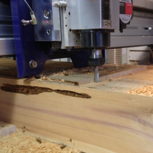 You can see how little clearance I had below the blue brackets.
As I said, I committed to using 6″ thick stock and a 2″ bit, but this meant that I needed to pay extremely close attention to the machine and anticipate where the collet might bottom out either on waste or the carved model itself. Some CAM software allows you to model your CNC machine so that you can verify if there will be any collisions ahead of time, but I didn’t have this feature.
This was a major time-sink since I had to babysit the machine much of the time, pausing the file occasionally while I manually hacked away at waste or other high spots.
Lesson learned: Next time I will use 4″ stock and 4″ bits.
Here’s how to figure out your maximum depth of cut.
Take your total Z travel (from the uppermost limit until the collet hits the table). In my case this is 8″. Divide that in half and you get 4″. This is both the thickest piece of stock you can cut as well as the longest bit you can use while still being able to move the bit up and over your stock without cutting it.
Routing the Tiki
ROUGHING IT OUT
I started with the roughing pass using a 1/2″ 2-flute square endmill. I set the max depth of cut per pass to 1/2″ (a general rule of thumb is you should not cut deeper than the diameter of the bit per pass). I set the stepover to 90% (90% of the bit is cutting fresh material on each pass) to get the job done quickly and started with a moderate feed rate of 2ips (Inches per second) and a spindle RPM of 14,000.
Feeds and Speeds: Roughing Pass
- Tooling: 1/2″ 2-flute square endmill
- Depth of Cut: 0.5″ (per pass)
- Stepover: 90%
- Feed rate: 2ips
- Spindle Speed: RPM 14,000 RPM.
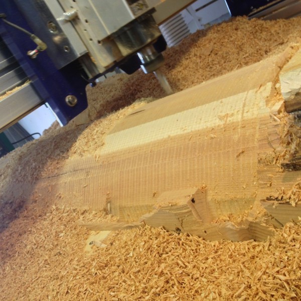 Lots of cedar chips!
Once the roughing pass was finished I switched to a 1/2″2-fluted ballnose bit for the finishing toolpath. I set the stepover to 10% to make sanding easier. I started at a moderate 2in/sec feed rate with a RPM set to 14,000. I was able to use a slightly longer bit now that the roughing pass was complete and there was a bit more space between the top of the model and the spindle bracket (the blue blur in the upper left of the photo below). This allowed me to complete the finishing pass with a minimal amount of babysitting. There were only a couple of areas where I was concerned about the collet bottoming out.
FINISHING
Feeds and Speeds: Finishing Pass
- Tooling: 1/2″2-fluted ballnose bit
- Depth of Cut: 0.5″ (per pass)
- Stepover: 10%
- Feed Rate: 2ips
- Spindle Speed: 14,000 RPM.
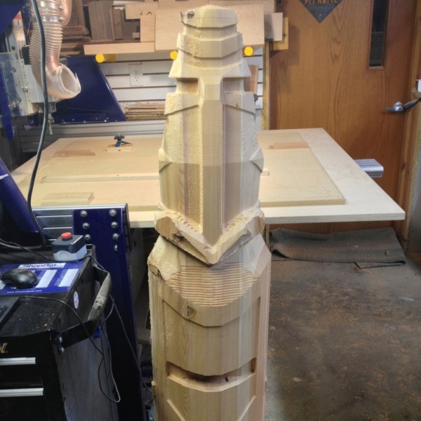 Front third carving complete.
REGISTERING THE TWO-SIDED MIDDLE SLICE
The center portion was machined on both the front and back sides. I used a fence that I attached to the table to register the middle section once I flipped it over. Because of the shape of the center section, there was a 2″ ridge of wood that could not be directly machined.
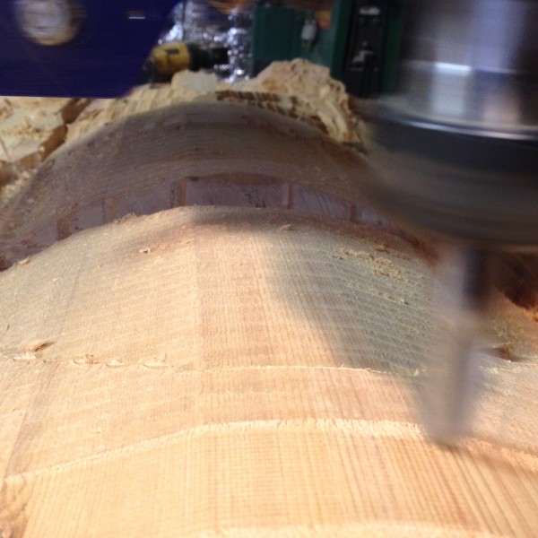
 Starting the finishing pass with a 1/2″ ballnose bit.
Assembly
Once all three slabs were shaped it was time to assemble the tiki. This was a bit of a challenge and required me to get creative with my clamping techniques. Two quarts of glue and a day later, I was ready to take the clamps off and do some hand-shaping.
Hand-shaping
I used a combination of hand scrapers, die grinders, and an angle grinder loaded with a sanding disc to remove the tool marks and add a few details to make it look more authentic.
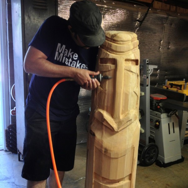 Lots of handwork. I had a great time doing this.
Finished Tiki
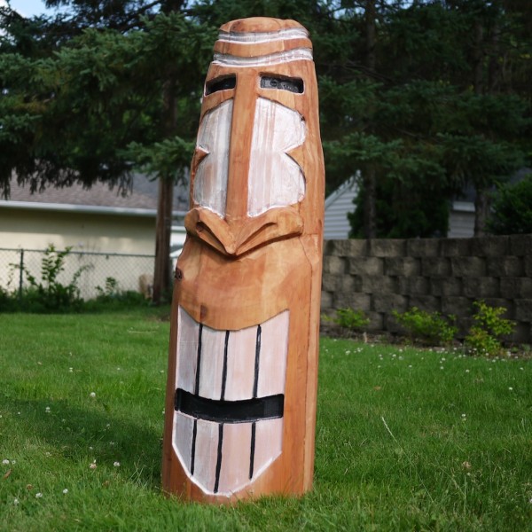
I finished the sculpture by applying a waterproofing deck finish and some black and white accents to make the Tiki’s features really pop.
The client was thrilled. I love to pop in from time to time for rummy cocktails and a look at the finished product perched above the tiki bar.
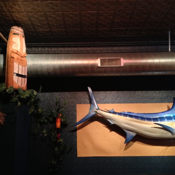 Resting in his perch above the bar with a nice view of the local wildlife.Cross-posted from http://makezine.com/magazine/routing-a-four-foot-tall-tiki-sculpture/